Welcome statement


Welcome to my blog on the building and sailing of a Goat Island Skiff (GIS). Join us on the Michael Storer Wooden Boat Plans forum or on Facebook, where the community of Storer Boat builders, owners, and admirers share their ideas, experiences, and watery hi-jinx.

If you are new to this blog, start at the beginning by selecting the oldest date in the blog archive located in the left-hand column. Enjoy!

Monday, May 7, 2012

Boat Wheels, pt.2: Because the boat doesn't occupy enough of my life...

While I was fortunate to find a trailer that is well suited to the GIS, that doesn't mean it's perfect...  Besides being covered in a considerable amount of surface rust, I came to notice that the design of the suspension is flawed.  Although the suspension is one of the features I like most about this trailer, the builder (home-built) did not locate the trailing arms correctly, resulting in contact and inevitable binding between the trailing arm and the frame.  Or at the very least, the frame prevents the trailing arm from moving at all, which is not how trailing arms are suppose to function.


So I decided to re-engineer the mounting points to allow freedom of movement:


Case closed

In a clear case of over thinking, I decided early on to integrate some out door carpet into the center case to cushion the dagger board from abrasion as well as adding friction to keep it from sliding up too easily.  I added additional space to the dimensions for the slot.  However, I was clearly winging it as far as how things would fit together, so I felt it would be wise to hold off final closing of the case until I could check the fit with the finished dagger board.  Just because the plans call for a certain size (plus an unknown thickness of glass and epoxy) doesn't mean MY board would match those dimensions.  In theory that logic seems sound, but in practice, I put off actually finishing the dagger board to the point where the rest of the hull is waiting.  Without the center case I can't install the middle seat which is one of the key parts to lock in the hull's shape.

Anyway, I went ahead and used the unshaped dagger board blank and the shaped rudder to check for fit, add the carpeting, and close it up.

Here's how much extra space (slot width) I built in, about 10mm or so:

With carpet on both sides of the board:

I reduced the length of the slot based on recent forum discussion regarding the amount of play fore and aft.  But I did leave enough room to avoid (I hope) making it too difficult to insert  and remove the blade:

But there's still the possibility of grounding damage that some have experienced leading edge top and trailing edge bottom:

I may install some bumpers, but I thought (over thought?) I'd take another another approach as well:


Even if they layers don't prevent wood-to-wood contact, they should prevent lateral slop.  I WON'T TOLERATE LATERAL SLOP!  (Sorry, I'm getting a little punchy...)

The rudder also gets the cushy treatment:


Bow Part 1

The instructions mention that it might be a good idea to cap the point of the bow with a strip of hardwood to provide protection for the end grain of the plywood sheets.  But it's given as a suggestion because the strength of the design and the use of fiberglass tape mean one can do without.  I'm doin' it.

One of the things I like about the GIS is how many individual touches I've seen builders use to make their boat unique.  The bow eye is an example where some interesting variations have popped up.  When I saw Paul Hayslett's Beautiful black boat in person at Mystic last summer, I fell in love with the Seadog bow eye he installed.  It actually took some time to find (West Marine was my source).

I give you now, Bow Part 1 (Parts 2 through x are yet to be created...)


Another significant leap of faith...


A little adjustment later...

My plan is to bring the cap/false stem to a blunt point--rounded enough for fiberglass tape to mold over smoothly--except around the bow eye where i will blend the wood to match the base.  That's the plan anyway...

Steps Part 2

As noted in Steps Part 1,the limber hole from the fore step emerges abaft of Bulkhead 1.  I placed the base of the fore step against the framing to properly locate the hole.


Below you see how it pops out relative to the main step.


Finally, here are the steps about to get a layer of glass before being glued together.  My thought is too reduce the amount of damage done by the base of the mast.  Wishful thinking maybe?


As mentioned in Part 1, the forward step requires some method for keeping the buoyancy tank airtight while still allowing the mast to pierce its space.  Enter the mast box.  The pics are self explanatory (I hope) but I will add that one step not completed is using fillets in the interior corners of the box, under the top flange, and where it meets the step when installed in position.


Steps Part 1

After much hand wringing and over-thinking, I've committed to making my GIS a yawl version as designed by Clint Chase and prototyped by John Goodman.  The main purpose for Clint's Yawl design was to ease the burden for the single handed sailor.  The mizzen mast can keep the hull hove to (i.e. pointed up into the wind) during operations that require the skipper to stop playing helmsman.  That might be to douse the main sail for reefing or it might be for lunch under way.  John Goodman has demonstrated the ability to put the boat into reverse, backing into a slip at the dock by manipulating his mizzen.

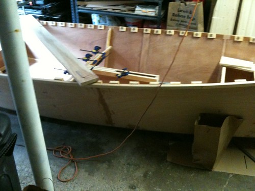
I may actually postpone the building of the mizzen mast and its sprit boom rig until later in the year (AFTER I launch...) but there are piece parts that I can install now while the hull is still coming together that will make yawling her later a simple matter of punching out some holes in the deck.  The extra pieces are the mast step and partner for the mizzen, and an additional step and partner for the main in a more forward position  (which maintains the helm balance of the boat when flying the mizzen).

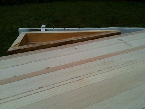
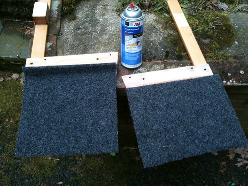
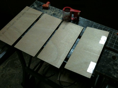
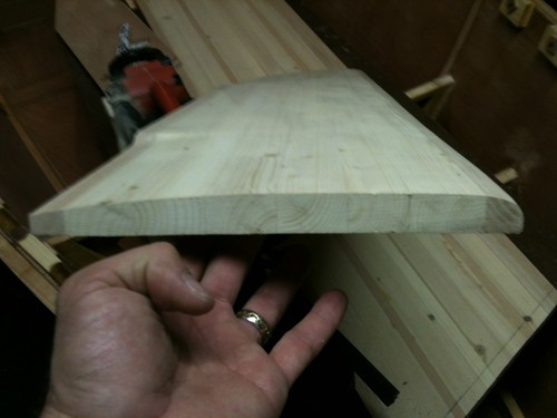
Here are the two fore steps (not the same as four two-steps as they might execute in Texas):


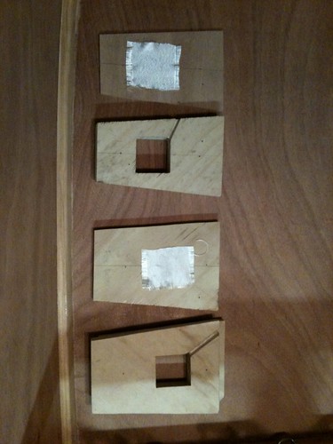
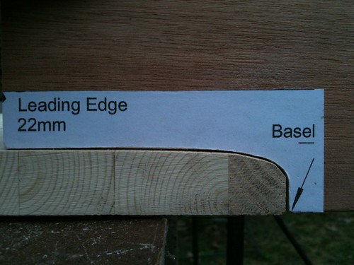
Above are the layers of the two steps, normal to the left, yawl to the right.  Per Storer, the step comprises a extra layer of 6mm ply on the bottom, followed by two 19mm layers that will be cut out to receive the mast base.  (I've used some quality plywood from a previous project because it was the right size.  I am depending on the epoxy encapsulation to keep it from de-laminating).  For the fore step, I needed to raise the height bit so I could direct the drainage properly.  I did so by using a 19mm base layer as well.


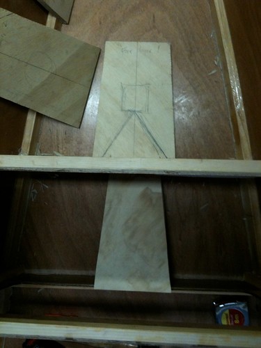
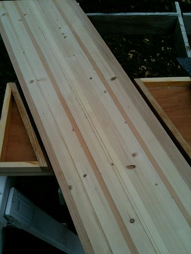
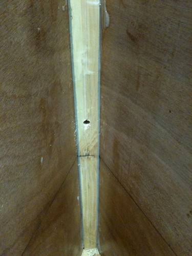
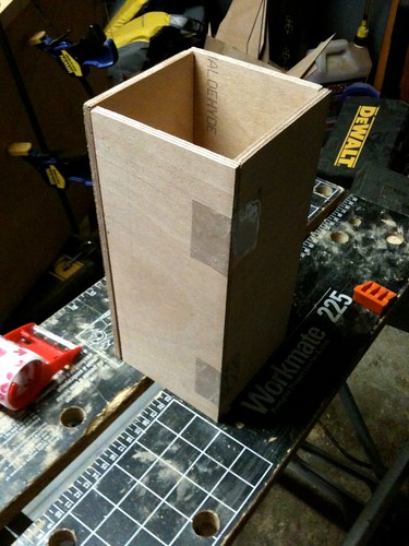
The diagonal lines above show the planned drainage path (although I only used one afterall).  The channel will meet up with a holle through the bulkhead's framing and will spill into the space behind the bulhead, alongside the normal mast step.  This should retain the airtight bouancy chamber forward of the bulkhead while keeping the step free of water.  That concept depends on a airtight tube running from the step to the deck which will be featured in a future post (it's built, I swear).


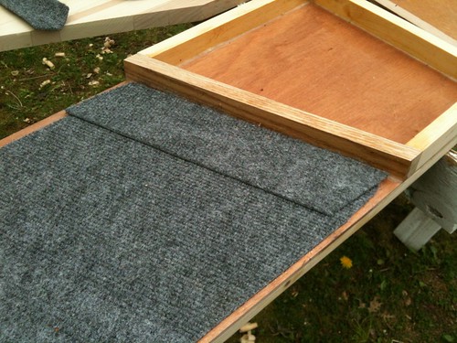
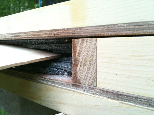
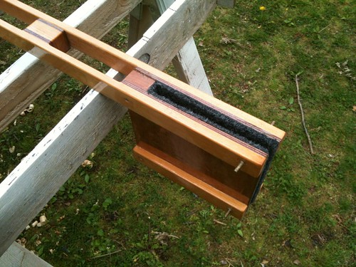
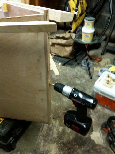
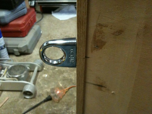
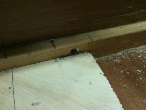
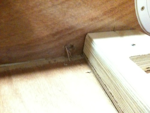
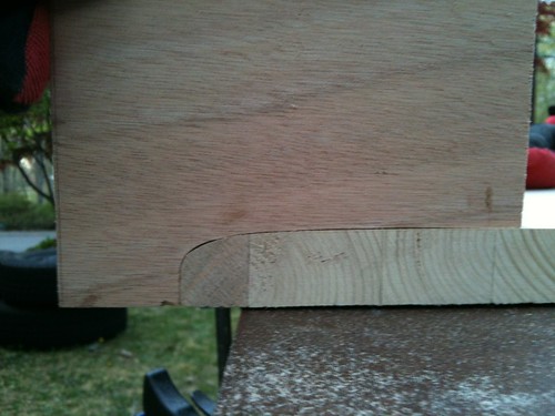
Here is the main step in position.  The careful observer will note the limber hole in the corner of the well.  The screws are simply holding the sandwich together before gluing.

There is more progress on steps and partners, but my photos are not all uploaded to Flickr yet.  Stay tuned for Steps Parts 2, 3, and beyond.

Foils

I have been putting off dealing with the rudder and daggerboard (collectively, blades or foils) for far too long.  I had made a conscious decision not to assemble the rudder box or the centercase until these foils were complete, but that strategy has created a bottleneck. A week ago I decided to overcome my fear of foils, and yesterday also decided to assemble the bigger parts without the completed foils.

I tackled the rudder first because it is smaller and I suspect not as critical to the boat's performance if I screw it up.  Using Storer's handy-dandy foil-o-matic gauge, I hit the leading edge with my belt sander and 50-grit paper.


I worked at opposite ends, leaving the middle untouched for awhile.  The middle was removed with a plane after I was comfortable with the shape of the ends.


I then proceeded to the trailing edge of the same face in the same manner.


The rest of the story (i.e. the opposite face) went the same.  For my daggerboard, I will alter the process slightly.  I will work both faces' ends before removing the middles.  I don't have photos for this post, but I kept the trailing edge squared off per Storer's instructions.  I still need to touch up the edges with a sanding block, but I'm confident enough to commence with the daggerboard soon.  Plus, I have to finish sanding the rudder so I can get some epoxy on it (and fiberglass, and more epoxy, and sanding, and... oy!)

Sunday, May 6, 2012

Behind in blogging, but not in building


I've been knocking out lots of little details since my last post.   It's staggering to think of all the little thing still remaining to be done.  I even made a list at one point of what were the absolute bare minimum essential tasks to get the thing floating and capable of sail.  But that didn't make the tasks go away.

I've also been jumping around to different areas of the boat (and trailer).  I have a bucket full of photos, but I'll keep to the minimum necessary to tell the tale.  The next few posts will be grouped by task/part rather than actual chronological order.


(which will be happening tomorrow because it's time for me to go to bed...)