Welcome statement


Welcome to my blog on the building and sailing of a Goat Island Skiff (GIS). Join us on the Michael Storer Wooden Boat Plans forum or on Facebook, where the community of Storer Boat builders, owners, and admirers share their ideas, experiences, and watery hi-jinx.

If you are new to this blog, start at the beginning by selecting the oldest date in the blog archive located in the left-hand column. Enjoy!

Sunday, April 22, 2012

Taking the Next Step

The next step was to turn the hull over (a family affair!) and install the bottom.  I set the three corner back on supports again, checked the level (which is when I noticed that BHD3 was not quite) and began planing down the chine logs.  Planing wood is a very satisfying task; everyone should plane some wood.

I used my trusty belt sander to finish off the chine logs and to level things out.  The hull bottom came next and confirm that things were fitting properly.  I marked off the frame locations on the bottom so I could be sure to screw into the frames.  Bag o' screws?  Check.  Bag o' pads?  Check.  Let the screwing begin!


As per plans, I then unscrewed half the panel, spread on the goo, and closed her up.

After a few days of curing, I hit the edges with the planes to trim the bottom to the sides.  Mmmm, planing.

All in

There's 3D, and there's 3D.  My last post had the appearance of being 3d, but without the glue it was all just for looks.  NOW, I can truly say I've gone 3D because I've glued the bulkheads in place and have glued the bottom on too.

I did a test of how well the proto hull came apart (partially) by unscrewing the stem and screwing it back together, then doing the same for BHD3.  Once I was convinced that the whole thing wouldn't crumple, I mixed up some glue and started at BHD3.

I thought in went back into place perfectly, but days later I noticed a slight shift on one side such that the BHD is a touch unlevel.  More importantly, the lower edge was lined up with the chines well enough that there would be no gap between the BHD and the bottom.  Other builders have been less fortunate.


After BHD3, I proceeded to the stem.  I only unscrewed one side at a time and it went back together nicely.
(Later, I filled the gap between the two chine logs with glue.)

I did one more part that evening, the transom.  My logic was to release those panels that would allow the remainder of the hull to keep its shape.  Once those three hardened, I then proceeded to the intermediate BHDs.  It's a technique that deviates from the instructions somewhat but that worked well for me.  I left the glue cure for a few days before taking the next step.

Sunday, April 8, 2012

DELTA-DELTA-DELTA!!!

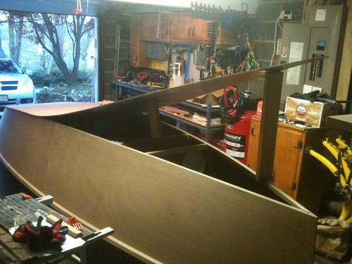
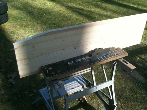
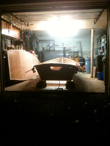
All good procrastination must come to an end sometime.  For no particular reason, I decided today would be the day to go 3D with my hull.  It took a couple of hours to clean and reorganize the garage first, but eventually I got down to the business of assembly.  I finally got my son Ruben involved since bending the plywood sides into shape is not easily done single handed.  I didn't take pictures of the process because I was too busy actually doing it and it took quite a bit of time and not a small amount of frustration.  But we finally got the sides to meet with bulkhead #1 and I screwed the parts into place.


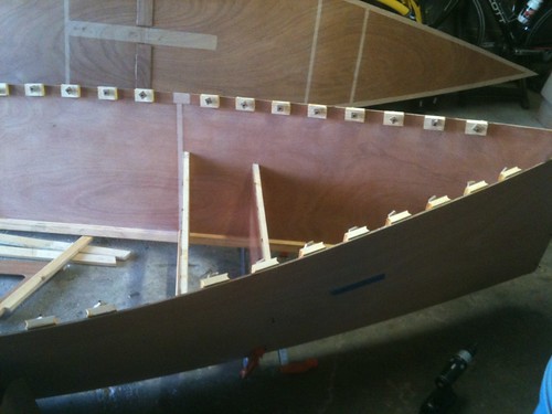
Step one (per the plans) is to attach both sides to the stem.  The fun begins when trying to get the sides to meet with the first bulkhead.  Eventually, we struck on a winning combination of two long bar clamps.  Each clamp has about 4" of screw threads to work with so we would tighten one up, get another unadjusted one cinched up and then tighten it another four inches.  As we got closer to our goal, the sides got more bent which means the clamps were trying to grip an angled surface and that's not what they like doing.  Ruben did a great job of holding the clamps in place, keeping them from slipping off (although they did occasionally succeed).  We found that it was helpful to run in a screw at the top corner of each side of the bulkhead.  This prevented the panel from sliding around but allowed for pivoting it into the correct alignment.  It was quite a challenge, but no cursing took place and we never gave up.  Father and son prevailed over the material world and it was quite satisfying to accomplish the task.   After that. the remaining bulkheads were much easier and my poor boy was able to get back to Call of Duty.


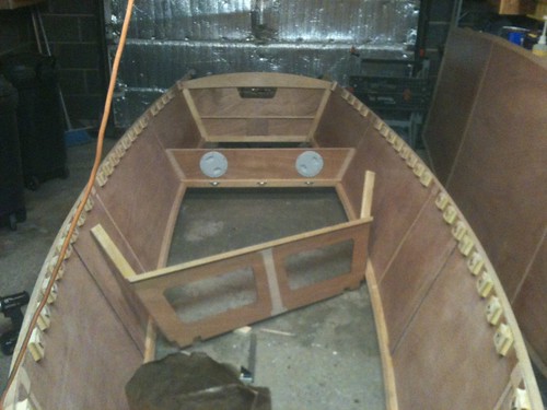
I used a technique described by other GIS builders online whereby clamps and straps combine to pull the two sides together.  Think I should have done this up front at BHD 1, although my straps are not ratcheting and I think I would not have been able to apply sufficient force to get the job done that way.  I recommend ratcheting straps to any GIS builders reading this.

The transom was also difficult to secure.  I called Ruben back into action and we pushed and pulled and grunted and complained (but never resorted to profanity!) and eventually we got it screwed into position.

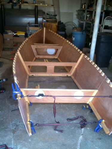
At this point it might be worthwhile to note that all this screwing is only temporary.  Each of the bulkheads will be glued in place; this is only a "dry run."  I will have to unscrew each of these parts, apply epoxy adhesive, replace the part and screw it down again.  Once the pox has hardened, the screws come out for good.  But before the glue can go on, the shape has to be fair and that is accomplished by fixing the gunwales into place.  Without them, the shape is very wavy, quite ugly, and just a little disconcerting.  It took a little coaxing to get the hull untwisted and I found that lifting the whole assembly off the ground with supports under just three points (because three point define a plane) was very helpful.  I placed bricks under the corners of the transom and at the stem.  Without them, the hull rests on it's lowest lines which are amidship at BHD 3.  I highly recommend raising the hull before trying to get things aligned.  I would now like to go on record as proclaiming that Michael Storer is quite a clever fellow.  Once that gun'l gets clamped into place, the line of the hull takes its proper shape and all is right in the world.


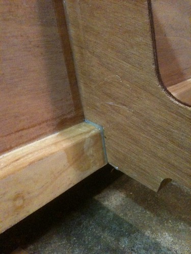
My technique for clamping the gun'l in place was to use screws through the inwale spaces I has previously installed.  Starting amidships at BHD 3, I clamped the gun'l over a two-foot section (one foot fore and aft of the bulkhead since that's the widest point in the curve) then drove the screws home.  I then worked my way to the rear, shifting the clamps and pulling the gun'l up into place.  My early work at marking the gun'l with the sheer line paid off today.  Another technique I borrowed from my predecessors was to leave the gun'l overly long and extending a foot or more aft of the transom.  This gives a place to pull the two sides together and it really works nicely.  Again, I used the straps-and-clamps technique.


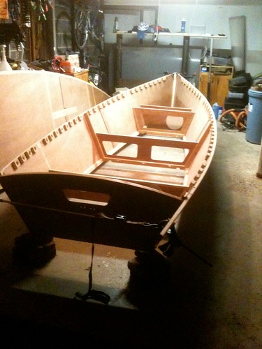
Things got a little interesting at the bow.  I haven't decided exactly hoe I want to finish off the gun'ls up front, so I wanted to leave them as long as possible.  My carpentry skills are not on par with Simon in Florida or George in England; I could not achieve the kind of point that they have.  I'll end up putting a cap at the tip, probably the same hardwood used to cap the gun'ls.


That's about it for now.  I should be gluing this baby together soon as long as it doesn't turn cold in the coming days.

Stay tuned...

Logistics, Logistics, Logistics


By the way, the wheels visible in the previous photos are my 3-season tires for my wife's minivan. I also spent some time today swapping out snow tires from two cars.

And if that's not enough, I have one eye on my trailer too. I have a concept for making a cradle that can 1) support the GIS hull both upright on its flat bottom and turtle on its gunwales, 2) safely secure the spars and mast and oars and foils and other paraphernalia. My vision is for two bulkheads that will align with the GIS #2 and #4 BHDs and three longitudinal tubes (PVC pipe?) that will span the bulkheads and carry the spars, mast, and oars. I think the fore bulkhead may be more of a locker that can store foils and gear, but the dagger board is so darn big, it might need a space of its own.

IMG_0602 by davlafont, on Flickr

The trailer is a nice size (recall that the mast is only slightly longer than the hull). I'll probably remove the winch post for something more fitted to the GIS hull.

IMG_0600 by davlafont, on Flickr

Not an excessive amount of overhang, but enough that I might need a removable light bar mounted to the hull.

IMG_0601 by davlafont, on Flickr

Of Blades and Foils


Pulled out my foil blanks and resumed work on them. The rudder has a touch of twist in it. I think it's slight enough that I can correct it during the shaping of the foil section. Here it is in outline:

IMG_0598 by davlafont, on Flickr

The daggerboard is still a hair thicker than 22mm. I can't be a perfectionist about this; I must move forward. I know the foil template is based on a 22mm thickness but I think I can get it right regardless. If you look closely you'll see a line along the bottom edge (left). That is the actual measured bottom edge, but I like Simon's technique of leaving a small bit extra that will stay flat. That way the board will be stable when it's flipped over. Of course, he also used a router for much of the rough shaping and I think I might go with a belt sander or plane ( or a combination).

IMG_0599 by davlafont, on Flickr

Little by little this thing will come together.